CNI, whose full name is Container Network Interface, is the API interface for container networks. The direction of kubernetes networking is to integrate different networking solutions by way of plugins, and CNI is the result of this effort. CNI focuses only on solving container network connectivity and resource release when containers are destroyed, providing a set of frameworks so that CNI can support a large number of different networking models and is easy to implement.
From the Network Model to CNI
Before understanding the CNI mechanism and specific implementation options such as Flannel, it is important to first understand the context of the problem, starting here with a review of the kubernetes network model.
Looking at the underlying network, kubernetes network communication can be viewed in three layers.
- intra-Pod container communication.
- Inter-Pod container communication with the host Pod.
- cross-host inter-Pod container communication.
For the first two points, the network communication principle is actually not difficult to understand.
- For intra-Pod container communication, since the containers inside the Pod are under the same Network Namespace (achieved through Pause container), i.e. sharing the same NIC, they can communicate directly.
- For inter-Pod container communication with the same host, Docker will create a Docker0 bridge on each host, and all the containers in the Pod on the host are connected to the bridge, so they can communicate with each other.
For the third point, cross-host container communication between Pods, Docker does not give a good solution, while for Kubernetes, cross-host container communication between Pods is a very important task, but interestingly, Kubernetes does not solve this problem itself, but focus on container orchestration issues, for cross-host container communication is This is the CNI mechanism.
CNI, which is the Container Network Interface, is the API interface for container networks. kubernetes networks are moving towards the integration of different network solutions through plugins, and CNI is the result of this effort.
CNI focuses only on solving container network connectivity and resource release when containers are destroyed, providing a set of frameworks so that CNI can support a large number of different network models and is easy to implement. Some of the more common CNI implementations are Flannel, Calico, Weave, etc.
CNI plug-ins are usually implemented in three modes.
- Overlay: relying on tunneling to get through and not relying on the underlying network.
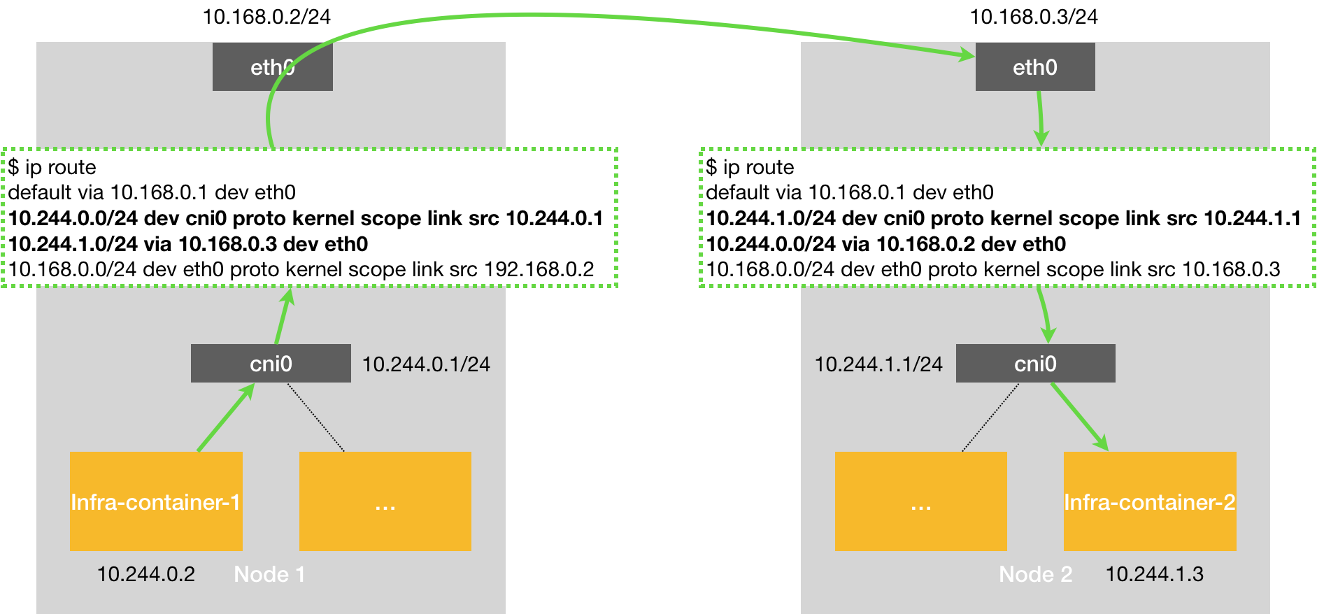
- Routing: hit by routing, partially dependent on the underlying network.
- Underlay: pass-through by the underlying network, with strong dependency on the underlying network.
When choosing CNI plug-ins, it is important to consider the actual needs, such as whether to consider NetworkPolicy to support the access policy between Pod networks, you can consider Calico, Weave; the creation speed of Pods, Overlay or routing mode CNI plug-ins are faster in creating Pods, Underlay is slower; network performance, Overlay performance is relatively poor, Underlay and routing mode are relatively faster.
How Flannel Works
A solution often seen in CNI is Flannel, introduced by CoreOS, which uses the Overlay network model described above.
Overlay network introduction
Overlay network is an application layer network, which is application layer oriented and does not consider the network layer, physical layer.
Specifically, an overlay network is a network that is built on top of another network. The nodes in this network can be seen as connected by virtual or logical links. Although there are many physical links at the underlying layer, these virtual or logical links correspond to paths one by one. For example, many P2P networks are overlay networks because they run on the upper layers of the interconnection network. Overlay networks allow routing information to a destination host that is not identified by an IP address, e.g. Freenet and DHT (Distributed Hash Table) can route information to a node that stores a specific file whose IP address is not known in advance.
Overlay networks are considered a way to improve interconnection network routing by allowing Layer 2 networks to pass through Layer 3 networks, addressing both the shortcomings of Layer 2 and the inflexibility of Layer 3.
How a Flannel Works
Flannel is essentially an overlay network, where TCP data is wrapped in another network packet for routing and communication, and currently supports UDP, VxLAN, AWS VPC and GCE routing.
Flannel runs a flanneld agent on each host that pre-assigns a subnet to the host and assigns an IP address to the Pod. flannel uses Kubernetes or etcd to store information such as network configuration, assigned subnets, and host public IPs. Packets are forwarded via VXLAN, UDP or host-gw type backend mechanisms.
Flannel specifies that individual Pods under a host belong to the same subnet and that Pods under different hosts belong to different subnets.
Flannel working mode
Supports 3 implementations: UDP, VxLAN, host-gw.
- UDP mode: uses device flannel.0 for packet decapsulation, not natively supported by the kernel, frequent kernel-user state switching, very poor performance.
- VxLAN mode: uses flannel.1 for packet unpacketization, not natively supported by the kernel, with high performance.
- host-gw mode: no need for intermediate devices like flannel.1, direct host as next-hop address of subnet, best performance.
The performance loss of host-gw is around 10%, while all other VxLAN “tunneling” based network solutions have a performance loss of around 20%-30%.
UDP mode
The UDP mode is officially not recommended anymore, the performance is relatively poor.
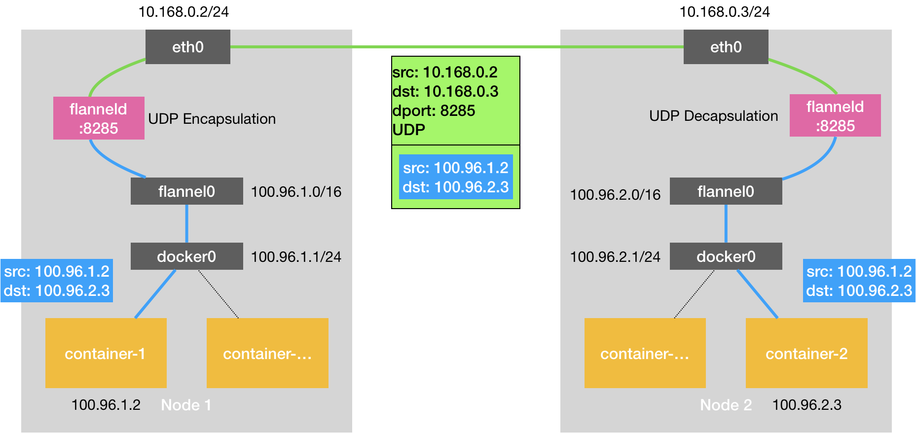
The core of the UDP mode is implemented through the TUN device flannel0, a virtual network device that works at layer 3 to pass IP packets between the operating system kernel and the user application. Compared to the direct communication between two hosts, there is an additional process of flanneld, this process, using the TUN device flannel0, only in the process of sending IP packets after multiple copies of data from the user state to the kernel state (linux’s context switching is more expensive), so the performance is very poor The principle is as follows.

Taking flannel0 as an example, the OS sends an IP packet to flannel0, which sends the IP packet to the application that created this device: the flanneld process (kernel state -> user state) Instead, the flanneld process sends an IP packet to flannel0, which appears in the network stack of the host, and then according to the routing table of the host The IP packet will appear in the host’s network stack and then proceed to the next step according to the host’s routing table (user state -> kernel state) Once the IP packet appears in the host from the container via docker0 and again according to the routing table into the flannel0 device, the flanneld process on the host receives the IP packet.
In a flannel-managed container network, all containers on a host belong to the “subnet” assigned to that host, and the correspondence between the subnet and the host is in Etcd (e.g. Node1’s subnet is 100.96.1.0/24, container-1’s IP address is 100.96.1.2).
When the flanneld process processes the incoming IP packet from flannel0, it can match the destination IP address (e.g. 100.96.2.3) to the corresponding subnet (e.g. 100.96.2.0/24) and find the IP address of the host corresponding to this subnet (10.168.0.3) from Etcd.
Then flanneld, after receiving the packet from container-1 to container-2, encapsulates this packet directly in a UDP packet and sends it to Node2 (the source address of the UDP packet, which is Node1, and the destination address is Node2).
The flanneld of each host is listening to port 8285, so the flanneld just sends the UDP to port 8285 of Node2. Then Node2’s flanneld sends the IP packet to its managed TUN device flannel0, which sends it to docker0.
VxLAN Mode
VxLAN, or Virtual Extensible LAN, is a network virtualization technology supported by Linux itself.
VxLAN can be fully encapsulated and decapsulated in the kernel state, thus building an Overlay Network through a “tunneling” mechanism.
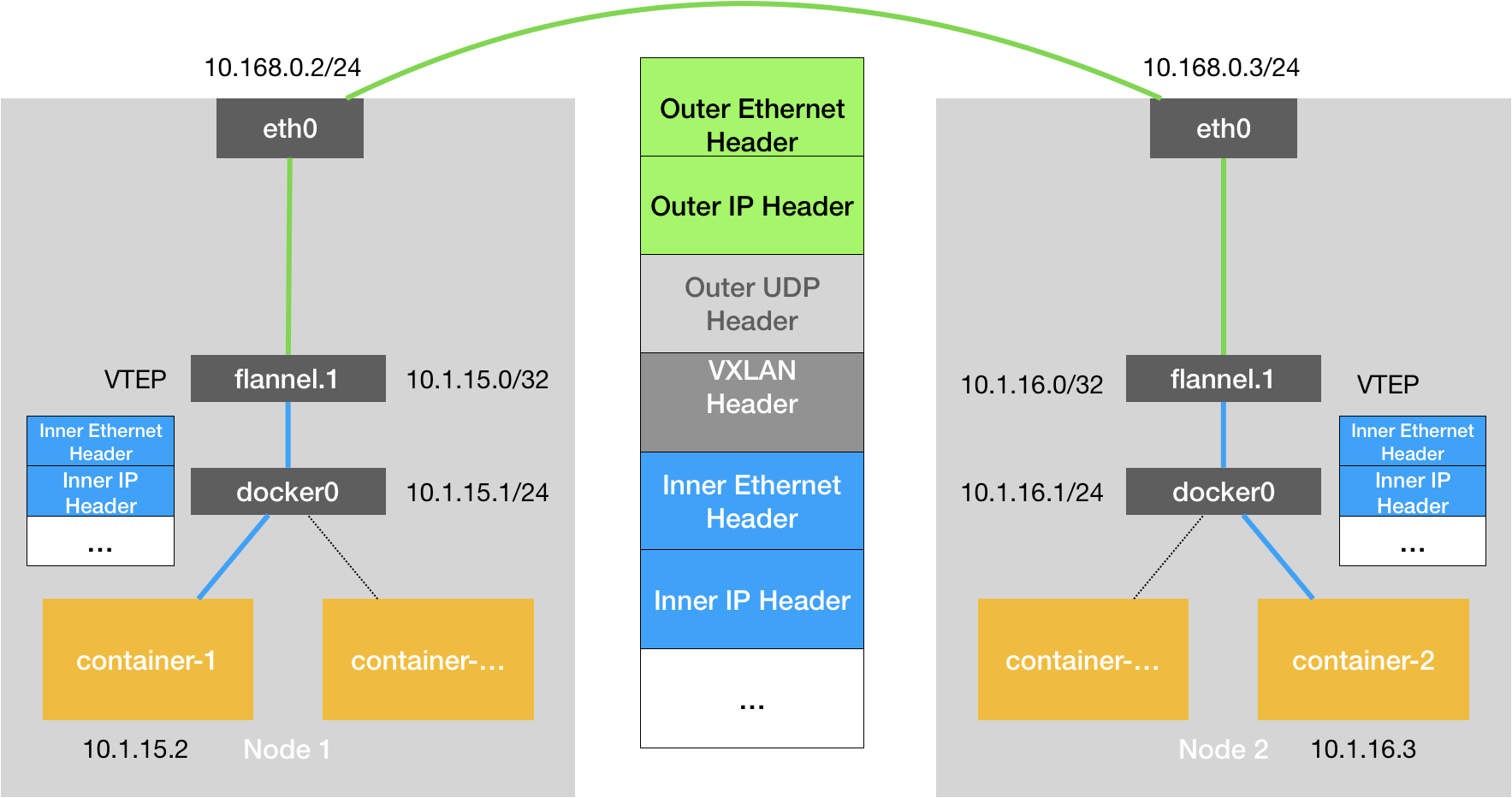
VxLAN is designed to “overlay” a virtual Layer 2 network maintained by the kernel VxLAN module on top of an existing Layer 3 network, so that “hosts” (virtual machines or containers) connected to this VxLAN Layer 2 network can work as if they were on the same network. can communicate as freely as if they were on the same local area network (LAN). In order to be able to “tunnel” over the Layer 2 network, VxLAN sets up a special network device on the host as the two ends of the “tunnel”, called VTEP: Virtual Tunnel End Point. The principle is as follows.

The flannel.1 device is the VTEP of the VxLAN, i.e. it has an IP address and a MAC address. Similar to the UDP mode, when the container-issues a request, the IP packet with the address 10.1.16.3 will first appear on the docker bridge and then be routed to the flannel.1 device on the local machine for processing (inbound). In order to encapsulate and deliver the “raw IP packets” to the normal host, the VxLAN needs to find the exit of the tunnel: the VTEP device of the host, which is maintained by the flanneld process of the host.
VTEP devices communicate with each other through Layer 2 data frames. After the source VTEP device receives the original IP packet, it adds a destination MAC address on it, encapsulates it into a leading data frame, and sends it to the destination VTEP device (to get the MAC address, you need to look up the Layer 3 IP address, which is the function of ARP table).

The encapsulation process only adds a layer 2 header, which does not change the content of the “original IP packet” The MAC address of the VTEP device, which has no practical meaning for the host network, is called an internal data frame, and cannot be transmitted in the host layer 2 network. The Linux kernel needs to further encapsulate it as an ordinary data frame of the host, so that it can carry the “internal data frame” through the eth0 of the host for transmission, Linux will add a dead VxLAN header in front of the internal data frame. It is an important identifier for VTEP to identify whether a data frame should be processed by itself or not. In Flannel, the default value of VNI is 1, which is why the host VTEP devices are called flannel.1.
A flannel.1 device only knows the MAC address of the flannel.1 device on the other end, but not the corresponding host address. In the linux kernel, the basis for forwarding by network devices comes from the FDB forwarding database, and the FDB information corresponding to this flannel.1 bridge is maintained by the flanneld process. The linux kernel then adds the Layer 2 data header to the front of the IP packet, filling in the MAC address of Node2. The MAC address itself is what Node1’s ARP table has to learn and is maintained by the flannel, and at this point the Linux encapsulated “external data frame” has the following format.

Then Node1’s flannel.1 device can send this data frame from eth0, and then through the host network to Node2’s eth0 Node2’s kernel network stack will find that this data frame has a VxLAN Header and a VNI of 1. The Linux kernel will unpack it, get the internal data frame, and according to the value of the VNI, all it hand over to Node2’s flannel.1 device
host-gw mode
The third protocol of Flannel is called host-gw (host gateway), which is a pure Layer 3 network solution, highest performance, i.e. Node nodes use their network interfaces as gateways to pods, thus allowing nodes on different nodes to communicate, this performance is higher than VxLAN because it has no additional overhead. However, it has a disadvantage that the node nodes must be in the same network segment.

The working principle of howt-gw mode is that the next hop of each Flannel subnet is set to the IP address of the host corresponding to that subnet, that is, the host acts as the “Gateway” of this container communication path, which is exactly what host-gw means. All the subnet and host information is stored in Etcd, and flanneld only needs to watch the changes of these data and update the routing table in real time. The core is the MAC address on the “next hop” setting of the routing table when the IP packet is encapsulated into a svine, so that it can reach the destination host through the layer 2 network.
In addition, if two pods are located in the same network segment, VxLAN can also support host-gw function, i.e., directly forwarding through the gateway of the physical NIC without tunnel flannel overlay, thus improving the performance of VxLAN, this flannel function is called directrouting.
Flannel communication process description
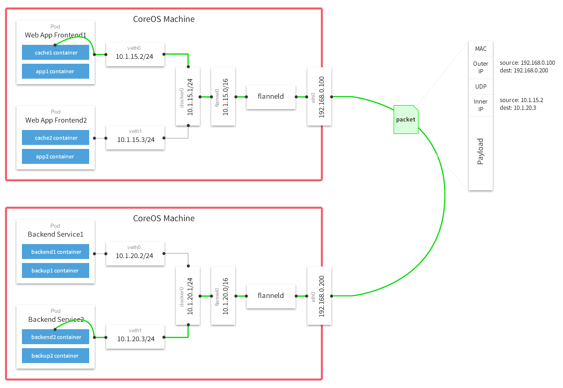
Using UDP mode as an example, the communication process between cross-host containers is shown in the following diagram.

The above diagram is a diagram of a packet in UDP mode provided by the Flannel official website after the packet sealing, transmission and unpacking, from this picture you can see that the two machines docker0 are in different segments: 10.1.20.1/24 and 10.1.15.1/24, if from the Web App Frontend1 pod (10.1 .15.2) to connect to the Backend Service2 pod (10.1.20.3) on another host, network packets from the host 192.168.0.100 to 192.168.0.200, the inner container packets are encapsulated into the host UDP, and wrapped in the outer layer of the host IP and mac address. This is a classic overlay network, because the container IP is an internal IP, can not communicate from across the host, so the container network interoperability, need to host to the host’s network .
Take the VxLAN mode as an example.
The data delivery process in the source container host.
-
The source container sends data to the target container, which is first sent to the docker0 bridge
To view the routing information in the source container content.
1$ kubectl exec -it -p {Podid} -c {ContainerId} -- ip route -
The docker0 bridge receives the data and forwards it to the flannel.1 virtual NIC for processing
After docker0 receives the packet, docker0’s kernel stack handler reads the destination address of the packet and sends the packet to the next routing node based on the destination address: View the routing information of the Node where the source container is located.
1$ ip route -
After receiving the data, flannel.1 encapsulates the data and sends it to eth0 of the host
After flannel.1 receives the data, flannelid encapsulates the packet into a Layer 2 Ethernet packet.
Ethernet Header information.
- From:{MAC address of the source container flannel.1 virtual NIC}
- To:{MAC address of the directory container flannel.1 virtual NIC}
-
Data encapsulated at the flannel routing node, re-encapsulated and forwarded to eth0 of the target container Node.
Since the current packets are only packets on the vxlan tunnel, they cannot be transmitted on the physical network yet. Therefore, the above packets need to be encapsulated again before they can be transmitted from the energy container node to the target container node, a job that is done by the linux kernel.
Ethernet Header information.
- From:{MAC address of the source container Node’s NIC}
- To:{MAC address of the Node Node of the directory container}
IP Header information.
- From:{IP address of the source container Node NIC}
- To:{IP address of the Node Node of the directory container}
With this encapsulation, it is possible to send packets over the physical network.
Data transfer process in the target container host.
- eth0 of the target container host receives the data, unwraps the packet and forwards it to the flannel.1 virtual NIC.
- flannel.1 virtual NIC receives the data and sends it to the docker0 bridge.
- finally, the data reaches the target container and completes the data communication between containers.