The two core issues that need to be addressed by container networks are as follows.
- the management of container IP addresses
- inter-container communication
Among them, the management of container IP addresses includes the allocation and recovery of container IP addresses. And the mutual communication between containers includes two scenarios: communication between containers of the same host and communication between containers across hosts. These two issues cannot be viewed completely separately either, as different solutions often have to consider both of these points.
The development of container network has been relatively mature, this paper will first give some overview of the mainstream container network model, and then will further explore the typical container network model.
CNM vs CNI
For container networks, docker and kubernetes propose separate specification standards.
- CNM(Container Network Model) used by docker
- The CNI model (Container Network Interface) supported by kubernetes
CNM is based on libnetwork, a model specification built into docker, and its general architecture is shown in the figure below.
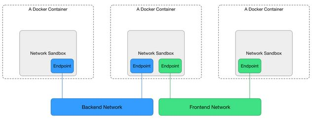
As you can see, the CNM specification defines the following three main components.
- Sandbox: Each Sandbox contains a container network stack configuration: container’s network port, routing table and DNS settings, etc. Sanbox can be implemented through Linux network namespace netns.
- Endpoint: Each Sandbox joins a Network through an Endpoint, which can be implemented through a Linux virtual network device veth pair.
- Network: A group of Endpoints that can communicate directly with each other, Network can be implemented through Linux bridge device bridge or VLAN etc.
As you can see, the underlying implementation principle is still the Linux virtual network device, network namespace, etc. that we introduced before. the typical scenario of CNM specification is like this: users can create one or more Networks, a container Sandbox can join one or more Networks through Endpoint, containers in the same Network Sanbox can communicate, and the container Sandbox in different Network is isolated. This allows decoupling from containers to networks, i.e. locks, before creating containers, you can create networks and then decide which network to let containers join.
But why kubernetes doesn’t use the CNM specification standard, instead opting for CNI, can be found on the official kubernetes blog Why Kubernetes doesn’t use libnetwork. kubernetes considers CNM to be somewhat too coupled with the container runtime, so a number of other organizations, led by kubernetes, have started working on a new CNI specification.
CNI is not natively supported by docker, it is a generic network interface designed for container technology, so the CNI interface can be easily called from the top to the bottom. However, getting from the bottom to the top is not as easy, so some common CNI plugins are difficult to activate at the docker level. However, both models support plugging, which means that each of us can write our own specific network implementations according to both sets of network specifications.
The network models natively supported by docker via libnetwork can be listed via docker network ls.
You can see that the default docker supports three network models, and you can specify the network model to be used by --network when you create the container. Bridge is the default. We will then describe and simulate the implementation of the bridge network model; the none network model does not create any network; and the host network model uses the host network, which does not create a new network namespace.
Note: If docker swarm is turned on, then you will also see the overlay network model, and we will cover the implementation of docker’s native overlay network model in more detail later.
bridge network
The bridge network model is the default network model of docker, if we do not specify the network model when creating containers, the bridge model will be used by default. bridge network model can solve the problem of communication between containers on a single host and the exposure of container services to the outside world, and its implementation principle is also very simple.
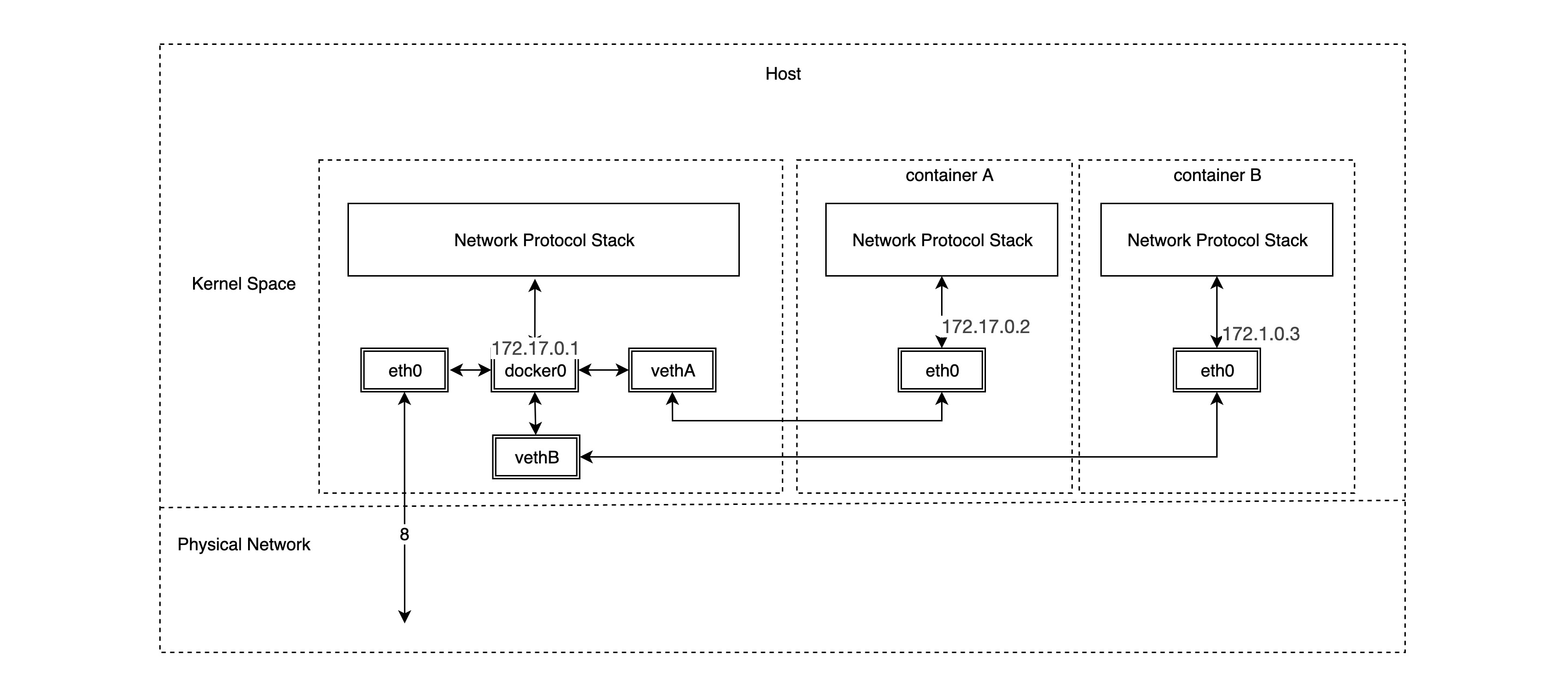
As you can see, the bridge network model relies heavily on the famous docker0 bridge and the veth virtual network device pair, and from our previous notes on Linux virtual network devices, we know that packets sent from one veth device pair will be sent directly to the veth device at the other end, even if they are not in a network namespace. space. So a veth device pair is actually a “network cable” that connects different network namespaces. docker0 bridge devices act as gateways to different container networks. In fact, once we create a container in bridge network mode, the corresponding veth device pair is automatically created, with one end connected to the docker0 bridge and the other end connected to the eth0 virtual NIC of the container network.
First we look at the bridge device docker0 and the routing rules on the host where docker is installed.
Then create a container using the default bridge network model and look at the veth device pair on the host side.
|
|
You can see that one end of the new veth device pair, veth42772d8, is already connected to the docker0 bridge, but what about the other end?
|
|
As we envisioned, the other end of the veth device pair is in the new network namespace 62fd67d9ef3e and has an IP address of 172.17.0.2/16, which is on the same subnet as docker0.
Note: If we create a symbolic link
/var/run/netns/that maps to/var/run/docker/netns/, we don’t have to use the nsenter command or go inside the container to see the other end of the veth device pair. You can view it directly using the iproute2 toolkit below.
1 2 3 4 5 6 7 8 9 10 11# ip netns show 62fd67d9ef3e (id: 0) default # ip netns exec 62fd67d9ef3e ip link show type veth 10: eth0@if11: <BROADCAST,MULTICAST,UP,LOWER_UP> mtu 1500 qdisc noqueue state UP mode DEFAULT group default link/ether 02:42:ac:11:00:02 brd ff:ff:ff:ff:ff:ff link-netnsid 0 # ip netns exec 62fd67d9ef3e ip addr show type veth 10: eth0@if11: <BROADCAST,MULTICAST,UP,LOWER_UP> mtu 1500 qdisc noqueue state UP group default link/ether 02:42:ac:11:00:02 brd ff:ff:ff:ff:ff:ff link-netnsid 0 inet 172.17.0.2/16 brd 172.17.255.255 scope global eth0 valid_lft forever preferred_lft forever
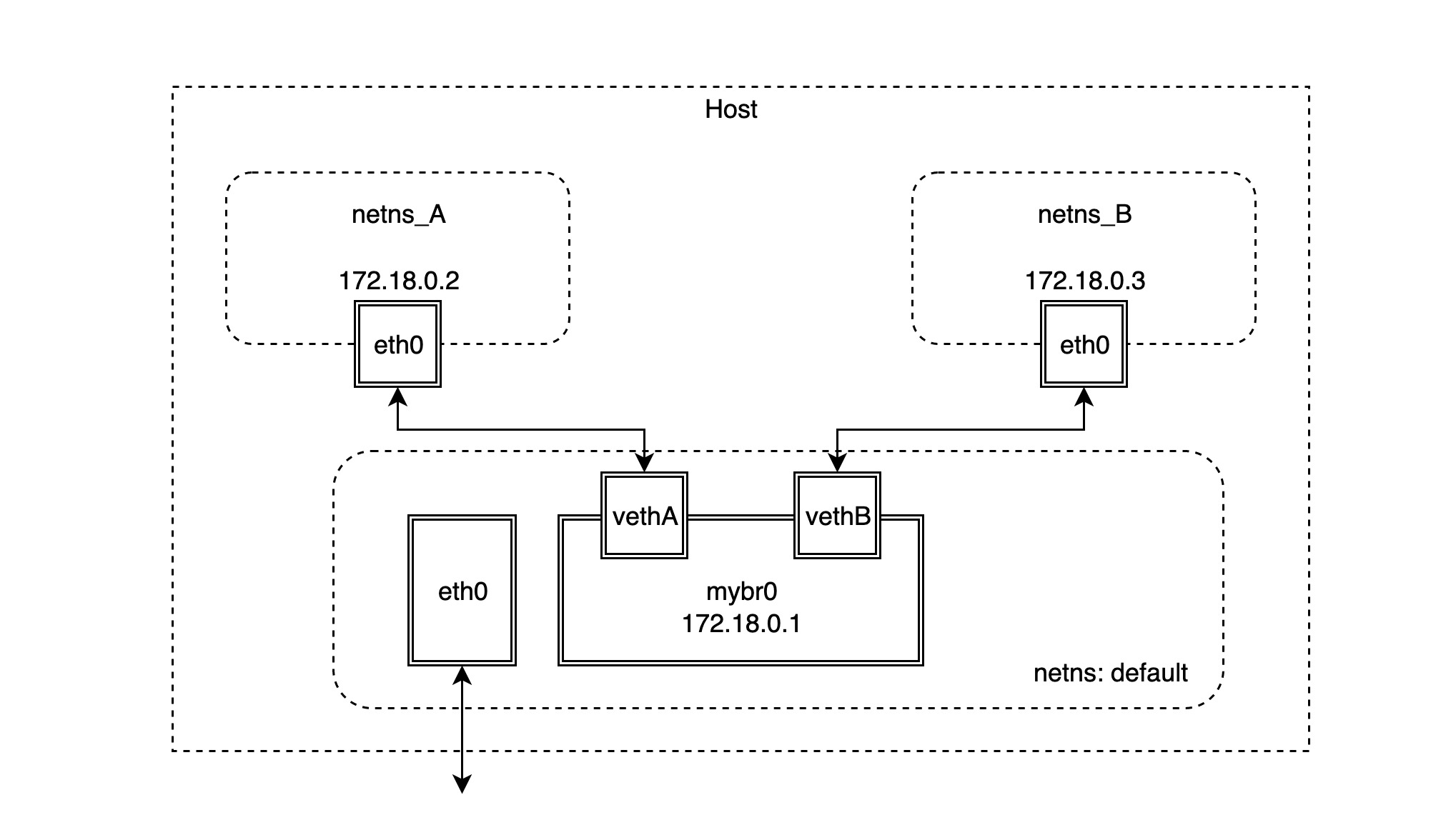
bridge network simulation
We will then simulate the implementation of the bridge network model. The basic network topology is shown below.
-
First create two netns network namespaces.
-
Create the bridge device mybr0 in the default network namespace and assign the IP address
172.18.0.1/16to make it the gateway of the corresponding subnet.1 2 3 4 5 6 7 8# ip link add name mybr0 type bridge # ip addr add 172.18.0.1/16 dev mybr0 # ip link show mybr0 12: mybr0: <BROADCAST,MULTICAST,UP,LOWER_UP> mtu 1500 qdisc noqueue state UNKNOWN mode DEFAULT group default qlen 1000 link/ether ae:93:35🆎59:2a brd ff:ff:ff:ff:ff:ff # ip route ... 172.18.0.0/16 dev mybr0 proto kernel scope link src 172.18.0.1 -
Next, create the veth device pair and connect it to the two network namespaces created in the first step.
1 2 3 4 5 6 7# ip link add vethA type veth peer name vethpA # ip link show vethA 14: vethA@vethpA: <BROADCAST,MULTICAST> mtu 1500 qdisc noop state DOWN mode DEFAULT group default qlen 1000 link/ether da:f1:fd:19:6b:4a brd ff:ff:ff:ff:ff:ff # ip link show vethpA 13: vethpA@vethA: <BROADCAST,MULTICAST> mtu 1500 qdisc noop state DOWN mode DEFAULT group default qlen 1000 link/ether 86:d6:16:43:54:9e brd ff:ff:ff:ff:ff:ff -
Connect one end of the veth device pair created in the previous step, vethA, to the mybr0 bridge and start it up.
-
Place the other end of the veth device pair, vethpA, in the network namespace netns_A and configure IP boot.
1 2 3 4 5 6 7 8 9# ip link set vethpA netns netns_A # ip netns exec netns_A ip link set vethpA name eth0 # ip netns exec netns_A ip addr add 172.18.0.2/16 dev eth0 # ip netns exec netns_A ip link set eth0 up # ip netns exec netns_A ip addr show type veth 13: eth0@if14: <BROADCAST,MULTICAST,UP,LOWER_UP> mtu 1500 qdisc noqueue state UP group default qlen 1000 link/ether 86:d6:16:43:54:9e brd ff:ff:ff:ff:ff:ff link-netnsid 0 inet 172.18.0.2/16 scope global eth0 valid_lft forever preferred_lft forever -
Access to the mybr0 gateway from the netns_A network namespace can now be verified.
1 2 3 4 5 6 7 8# ip netns exec netns_A ping -c 2 172.18.0.1 PING 172.18.0.1 (172.18.0.1) 56(84) bytes of data. 64 bytes from 172.18.0.1: icmp_seq=1 ttl=64 time=0.096 ms 64 bytes from 172.18.0.1: icmp_seq=2 ttl=64 time=0.069 ms --- 172.18.0.1 ping statistics --- 2 packets transmitted, 2 received, 0% packet loss, time 1004ms rtt min/avg/max/mdev = 0.069/0.082/0.096/0.016 m -
If you want to access addresses other than
172.18.0.0/16from the netns_A network namespace, you need to add a default default route.Note: If you try to ping another public address, such as
google.com, it will fail. The reason is that the source address of the pinged packet (ICMP packet) has not done source address translation (snat), so the ICMP packet has no return; docker implements source address translation by setting iptables. -
Next, follow the steps above to create the connection default and netns_B network namespace veth device pair.
1 2 3 4 5 6 7 8 9 10 11 12 13 14 15 16# ip link add vethB type veth peer name vethpB # ip link set dev vethB master mybr0 # ip link set vethB up # ip link set vethpB netns netns_B # ip netns exec netns_B ip link set vethpB name eth0 # ip netns exec netns_B ip addr add 172.18.0.3/16 dev eth0 # ip netns exec netns_B ip link set eth0 up # ip netns exec netns_B ip route add default via 172.18.0.1 # ip netns exec netns_B ip add show eth0 15: eth0@if16: <BROADCAST,MULTICAST,UP,LOWER_UP> mtu 1500 qdisc noqueue state UP group default qlen 1000 link/ether 0e:2f:c6🇩🇪fe:24 brd ff:ff:ff:ff:ff:ff link-netnsid 0 inet 172.18.0.3/16 scope global eth0 valid_lft forever preferred_lft forever # ip netns exec netns_B ip route show default via 172.18.0.1 dev eth0 172.18.0.0/16 dev eth0 proto kernel scope link src 172.18.0.3 -
By default, Linux disables the forwarding function of the bridge device bridge, so you cannot ping netns_B in netns_A. You need to add an additional iptables rule to activate the forwarding function of the bridge device bridge.
1# iptables -A FORWARD -i mybr0 -j ACCEPT -
It is now possible to verify that two network namespaces can communicate with each other.
1 2 3 4 5 6 7 8 9 10 11 12 13 14 15 16# ip netns exec netns_A ping -c 2 172.18.0.3 PING 172.18.0.3 (172.18.0.3) 56(84) bytes of data. 64 bytes from 172.18.0.3: icmp_seq=1 ttl=64 time=0.091 ms 64 bytes from 172.18.0.3: icmp_seq=2 ttl=64 time=0.093 ms --- 172.18.0.3 ping statistics --- 2 packets transmitted, 2 received, 0% packet loss, time 1027ms rtt min/avg/max/mdev = 0.091/0.092/0.093/0.001 ms # ip netns exec netns_B ping -c 2 172.18.0.2 PING 172.18.0.2 (172.18.0.2) 56(84) bytes of data. 64 bytes from 172.18.0.2: icmp_seq=1 ttl=64 time=0.259 ms 64 bytes from 172.18.0.2: icmp_seq=2 ttl=64 time=0.078 ms --- 172.18.0.2 ping statistics --- 2 packets transmitted, 2 received, 0% packet loss, time 1030ms rtt min/avg/max/mdev = 0.078/0.168/0.259/0.091 ms
In fact, the two network namespaces are in the same subnet at this point, so the bridge device mybr0 is still working at layer 2 (data link layer) and only needs the MAC address of the other party to access it.
But if you need to access addresses in other network segments from both network namespaces, this is where the bridge device mybr0 set as the default gateway address comes into play: packets from both network namespaces find that the destination IP address is not the address of the local subnet and are sent to the gateway mybr0. At this point, the bridge device mybr0 is actually working at layer 3 (IP network layer), and after it receives the packet, it looks at the local route and the destination IP address to find the address of the next hop.